User guide: Summit-XL
The Summit-XL is a mid-sized differential-drive wheeled robot produced by Robotnik. The robot is capable of performing field robotics tasks both in the context of research developments or solutions for the industry. It is endowed with an onboard computer, traction in the four wheels, and a set of sensors that enable it for operating in indoor and outdoor environments. The Summit-XL, and its main components are indicated below.
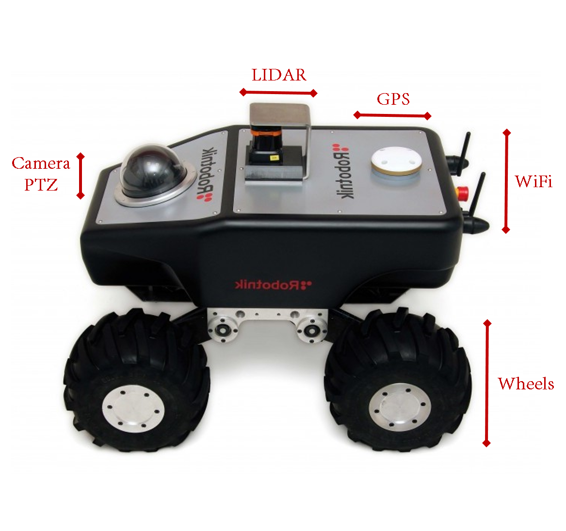
In this course, you will use the wheels of the robot to navigate the scenarios, the pan-tilt-zoom (PTZ) camera to visualize the scenarios, and the laser range finder (LIDAR) to detect objects on its surroundings. The software architecture of the robot is structured within the Robot Operating System (ROS), and you will simulate the platform using Gazebo
The Robot Operating System (ROS)
ROS is a set of libraries and tools for the development of robotics systems. In the last years, it has become the standard framework to design and implement robotic platforms such as humanoid robots, drones, underwater vehicles, mobile manipulators, among others. You can find a list of known robotic platforms using ROS here.
ROS is particularly interesting because it provides a full ecosystem for the development of robotics. It is platform-independent and has tools that work at different levels of the system management: hardware abstraction; low-level control; message-passing between processes; package management; and implementations of several robotics libraries. A large community of researchers and developers constantly create new software packages that enable perception, mapping and navigation capabilities—that can be combined in a modular way and with different autonomy levels. The code can be later re-used with minimal or no modification whatsoever.
As mentioned above, ROS is platform-independent and it can also be used with almost any robotics simulator. In this course you will use Gazebo 9.0. ROS already integrates plugins and interfaces to conduct simulations in Gazebo, and Robotnik has released the simulation models of the Summit XL.
You will use ROS to develop the control software for the Summit-XL. However, a complete learning on how to use ROS for developing robotic platforms is out of the scope of this course. If you are further interested in ROS, you can take a look to the MOOC of TU Delft—The Netherlands, and the official ROS tutorials.
You have two options to interact with the Summit-XL in ROS: using command lines in the Linux terminal; or using scripts that are written in Python. In the following you will find the commands lines to control and monitoring the robot. The use of scripts will be further explained while developing the practical sessions.
Coordinate frames
An important concept to understand how the robot operates in the environment is the one of coordinate frames. A coordinate frame is a coordinate system that describes the spatial distribution of objects with respect to an arbitrary position. While working with mobile robots, you will often use at least two different frames: the coordinates in the frame of the world, and the coordinates in the frame of the robot.
The coordinates in the frame of the world describe how the robot is positioned with respect the origin of its workspace—that is, the coordinate (0,0,0). For example, this reference frame is often established by navigation systems that provide global information such as GPS, GLONASS and [Galileo](https://en.wikipedia.org/wiki/Galileo_(satellite_navigation).
The coordinates in the frame of the robot describe the position of objects with respect to the origin of the body of the robot—that is, the inner coordinate (0,0,0) of its body. Commonly, the origin a robot is located on the center of its body in the (x,y,z) axes. This allows to simplify the computation of the kinematic and dynamic behavior of the robot.
The image below shows the frame of the world—the coordinate system with respect to the origin of the world simulated in Gazebo; and the frame of the Summit-XL—the coordinate system with respect of the origin of the robot.
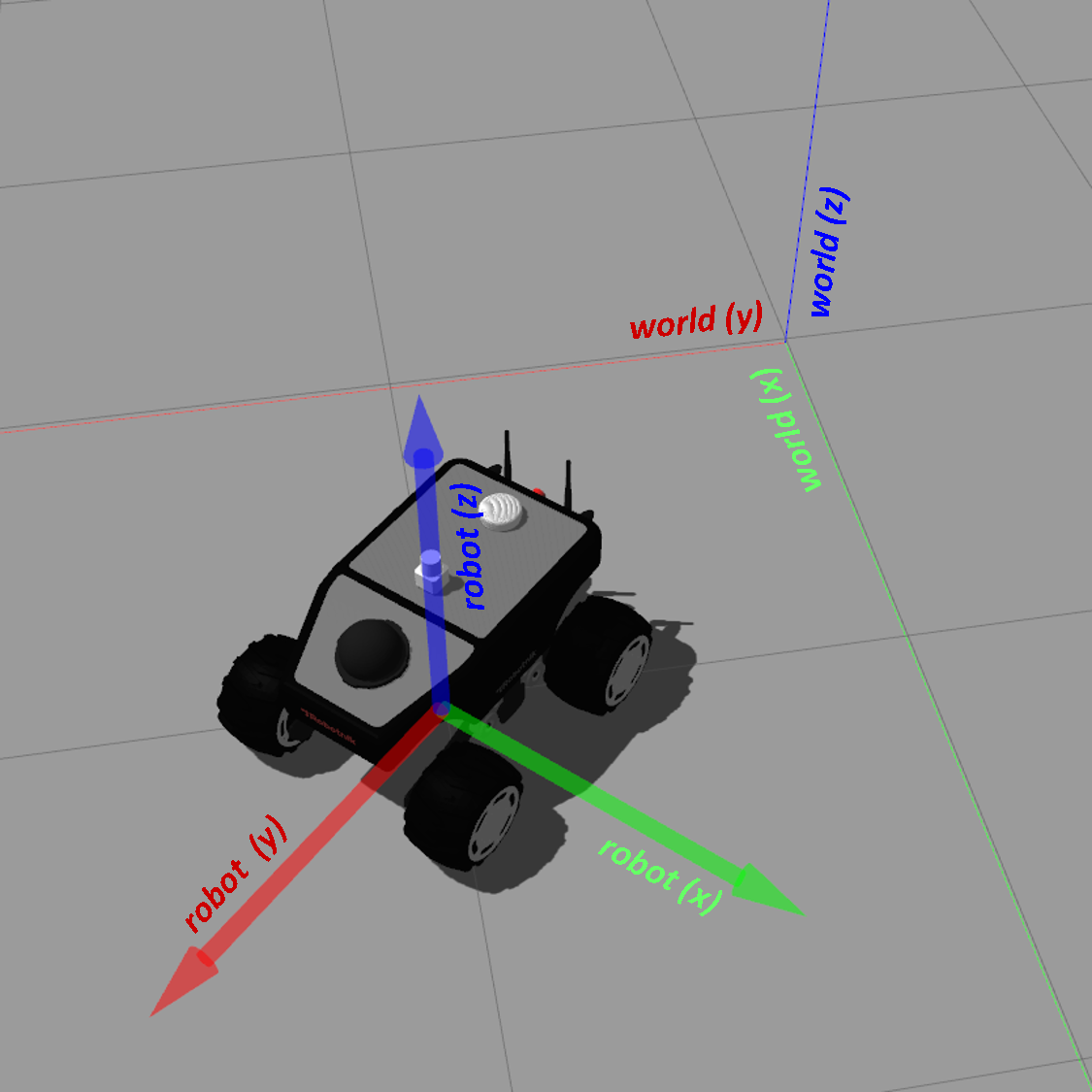
In this picture, the robot is positioned at (1,1,0) and it is rotated 45° with respect the world frame. The red arrow indicates the x axis, the green arrow indicates the y axis, and the blue arrow indicates the z axis. In all cases, the coordinate frames follow the right hand rule.
Note that the two coordinate frames are independent from each other. The position and orientation of the robot with respect to the origin of the world will change as the robot moves. However, the position of the robot with respect to its own coordinate frame remains always constant—the center of the robot it is always positioned in the coordinate (0,0,0).
A further description of coordinate frames in ROS is provided in the documentation for Standard Units of Measure and Coordinate Conventions.
Moving the Summit-XL
The robot embeds a low-level controller that transforms high-level velocity commands into the corresponding wheel velocities. You can command the movement of the robot by defining a linear velocity on its x axis and an angular velocity around its z axis. The movement of the robot results from the movement described by its linear velocity Vx and its angular velocity Wz. These velocities are described in the coordinate frame of the robot—and schematic is provided below.
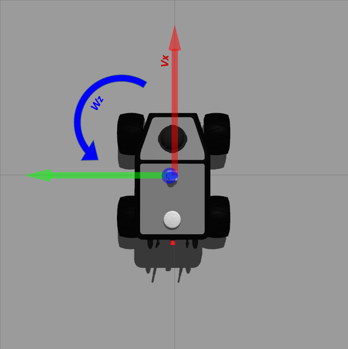
In the Summit-XL, the linear velocity Vx has values in the range [-3.0,3.0] m/s: positive values of Vx drive the robot to move forward and negative values drive the robot backwards. The angular velocity Wz has values in the range [-6.0,6.0] rad/s: positive values of Wz turn the robot to the left and negative values turn the robot to the right.
If you only command a linear velocity, the robot will move straight in the direction that you indicate. On the other hand, if you only command the angular velocity, the robot will rotate in place. Finally, if you command the linear and angular velocity at the same time, the robot will move following an arch trajectory.
- Setting the velocity of the robot from the command line
After starting the simulation, you can control the velocity of the robot using command lines in the Linux terminal. The command line has the following structure
rostopic pub /robot/cmd_vel geometry_msgs/Twist "linear:
  x: 0.0
  y: 0.0
  z: 0.0
angular:
  x: 0.0
  y: 0.0
  z: 0.0" -r 10
Where linear: x: indicates the linear velocity Vx and angular: z: indicates the angular velocity Wz. You can set their values and move the robot accordingly.
For example, if you want to move forward the robot at 0.3 m/s, you can type
rostopic pub /robot/cmd_vel geometry_msgs/Twist "linear:
  x: 0.3
  y: 0.0
  z: 0.0
angular:
  x: 0.0
  y: 0.0
  z: 0.0" -r 10
The velocity command will be send continuously to the robot until you press Ctrl + C. In other words, you can press Ctrl + C to stop the robot after it starts moving.
If you wish you turn the robot to the left at 0.3 rad/s, you can type
rostopic pub /robot/cmd_vel geometry_msgs/Twist "linear:
  x: 0.0
  y: 0.0
  z: 0.0
angular:
  x: 0.0
  y: 0.0
  z: 0.3" -r 10
Finally, if you want to drive the robot following the an arc trajectory to the back and to the right, you can set the value of the two velocities
rostopic pub /robot/cmd_vel geometry_msgs/Twist "linear:
  x: -0.3
  y: 0.0
  z: 0.0
angular:
  x: 0.0
  y: 0.0
  z: 0.3" -r 10
Due to the length of the command line, it could be easier to type it using auto-completion in the terminal. To do so, type rostopic pub /robot/cmd_vel and press the key TAB until the complete structure of the message appears. Afterwards, you can set your the desired values and add the argument -r 10 at the end of the line.
PTZ camera
The Summit-XL embeds a pant-tilt-zoom camera. The camera allows you to visually perceive the environment from the perspective of the robot. You can visualize images streamed from the camera with the command
rosrun image_view image_view image:=/robot/robot_front_ptz_camera/image_raw
A new window will spawn with the streaming of images as they are captured from the camera of the robot.
You can control the pan and tilt of the camera: the pan refers to the orientation of the camera in the horizontal axis of the image; and the tilt refers to the inclination of the camera in the vertical axis. The input to control the pan and tilt is the desired angular position (rad) of the camera with respect to the center of the image—as it is positioned at the initialization of the robot. The camera of the robot starts in the position (0,0) rad.
The command line to set the pan of the camera is written below
rostopic pub /robot/joint_pan_position_controller/command std_msgs/Float64 "data: 0.0"
Likewise, you can type the following command to control the tilt of the camera
rostopic pub /robot/joint_tilt_position_controller/command std_msgs/Float64 "data: 0.0"
The pan and tilt of the camera can be set independently in the range [-1.57,1.57]. A negative value of the pan turns the camera to the left, with respect to the center of the image; and positive values for the pan turn the camera to the right. In the case of the tilt, negative values incline the camera to the floor, and positive values incline it towards the ceiling.
If you want to turn the pan to 90° (1.57 rad) to the left, you can type
rostopic pub /robot/joint_pan_position_controller/command std_msgs/Float64 "data: 1.57"
and, if you wish to rise the inclination of the camera to 22.5° (0.393 rad), you can type
rostopic pub /robot/joint_tilt_position_controller/command std_msgs/Float64 "data: 0.393"
Bear in mind that it is possible to set the pan and tilt to camera positions that point towards places out of the real field of view of the robot. For example, if the camera points towards inside of the robot. In these cases, the behavior of the camera is unpredictable and the images can be considered not meaningful.
LIDAR
The Summit-XL is endowed with a laser range finder (LIDAR) that can detect obstacles around the robot in a circular pattern of 360°. The readings of the LIDAR are defined in the range [0.07,10] m. In the image below shows the readings obtained with the LIDAR when the robot is surrounded by three cubes.
You will not interact directly with the LIDAR of the robot. However, it is a sensor that will be used in the practical session P1.2 to build occupation maps of the workspace of the robot.
Designing control software for the Summit-XL using Python
You can also send commands to the robot by using control software. In this sense, you can control the Summit-XL with Python scripts that integrate the ROS libraries. The ROS libraries handle the reception and transmission of messages between the control software that you might develop and the simulated robot.
During the practical sessions you will produce control software that is structured in two parts: a first part of the code handles the ROS libraries and interactions with Gazebo; and a second part corresponds to the code that you will implement. For each practical session, you will be provided with scripts that already implement the ROS libraries that are required to develop the task at hand. The scripts contain an explanation of the functionalities you must develop, and indicate where you must place your code. In all cases, you will just implement basic programming structures and you will only require basic knowledge on mathematics and geometry.