User guide: The foot-bot
The foot-bot is a differential-drive wheeled robot specifically designed to conduct experiments with robot swarms. The robot is endowed with sensors and actuators that enable it to interact with other foot-bots and with the environment. The foot-bot, and its sensors and actuators are indicated below.
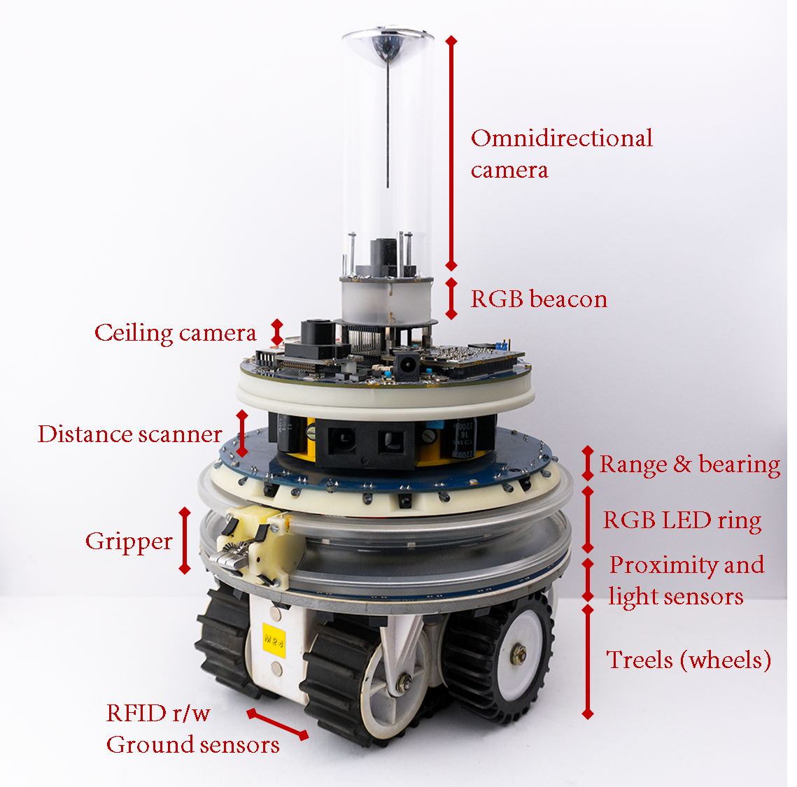
In this course, you will use the wheels of the robot to navigate the scenarios, the proximity sensors to detect objects near the robot, the light sensors to measure the intensity of ambiance light, the ground sensors to identify the color of the floor, the RGB LEDs to display color lights and the omnidirectional camera to perceive those color lights, and finally, the range-and-bearing system to locate and communicate with other robots in the surroundings.
Designing control software for the foot-bot
The control software of the foot-bot will be developed in ARGoS by using the programming language LUA. After designing the control software for one robot, the controller will be ported automatically to all the robots in the swarm. The robot-related LUA functions are described in the following.
Data structure
The robot-related functions and data are stored in the table robot. For instance, to set the robot wheel speed, you need to call
robot.wheels.set_velocity(5,5)
Analogously, if you wish to store the reading of the 4th proximity sensor in a variable named r, you can type
r = robot.proximity[4].value
Important note:
Never write directly into the robot attributes—that is, never assign a value to the reading of a sensor. For instance, the following line is an error.
robot.proximity[4].angle = 1.67
Never apply operations such as table.sort() to the robot table. For instance, the following line is an error.
table.sort(robot.proximity, function(a,b) return a.value > b.value end)
If you intend to use the values of a robot table, copy that table first as indicated in the following lines.
myprox = table.copy(robot.proximity)
table.sort(myprox, function(a,b) return a.value < b.value end)
Robot ID
A string containing an unique ID for each robot.
robot.id
Wheels
The real robot moves using two sets of wheels and tracks called treels. For simplicity, we treat the treels like normal wheels. The state of the wheels is indicated by the table
robot.wheels
You can move the robot by using the function set_velocity(l,r)—where l and r are the left and right wheel velocity, respectively. By ‘wheel velocity’ we mean linear velocity. For instance, to move the robot forward at 5cm/s you can write
robot.wheels.set_velocity(5,5)
The robot provides information about its motion and wheel state. The distance between the two wheels in cm is given by
robot.wheels.axis_length
the current wheel velocity is stored in
robot.wheels.velocity_left
robot.wheels.velocity_right
and the linear distance covered by the wheels in the last time step is indicated by
robot.wheels.distance_left
robot.wheels.distance_right
Proximity sensors
The proximity sensors detect objects around the robots. The state of the proximity sensors is indicated by the table
robot.proximity
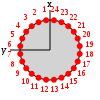
The robot has 24 proximity sensors equally, distributed in a ring around the robot body. Each sensor has a range of 10cm and returns a reading composed of an angle in radians and a value in the range [0,1]. The angle corresponds to where the sensor is located in the body with respect to the front of the robot, which is the local x axis. Regarding the value, 0 corresponds to no object being detected by a sensor, while values > 0 mean that an object has been detected. The value increases as the robot gets closer to the object.
For example, to access the angle of the first proximity sensor you can write
robot.proximity[1].angle
and to access the value of the first proximity sensor you can write
robot.proximity[1].value
Light sensors

The light sensors allow the robot to detect the intensity and location of ambiance light sources. The state of the proximity sensors is indicated by the table
robot.light
The robot has 24 light sensors, equally distributed in a ring around its body. Each sensor reading is composed of an angle in radians and a value in the range [0,1]. The angle corresponds to where the sensor is located in the body with respect to the front of the robot, which is the local x axis. Regarding the value, 0 corresponds to no light being detected by a sensor, while values > 0 mean that light has been detected. The value increases as the robot gets closer to a light source.
For example, to access the angle of the first light sensor you can write
robot.light[1].angle
and to access the value of the first light sensor you can write
robot.light[1].value
Ground sensors
The ground sensors read the color of the floor in a gray-scale. The state of the ground sensors is indicated by the table
robot.motor_ground
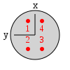
The ground sensor corresponds to a list of 4 readings, each containing a table composed of value and offset. The value ranges in different shades of gray that go from 0 to 1, where 0 means black, and 1 means white. The offset corresponds to the position read on the ground by the sensor. The position is expressed as a 2D vector stemming from the center of the robot. The vector coordinates are in cm.
For example, to access the value of the first ground sensor you can write
robot.motor_ground[1].value
and to access the value of the first proximity sensor you can write
robot.motor_ground[1].offset
Range-and-bearing system
The range-and-bearing system allows robots to perform localized communication. Localized communication means that a robot, upon receiving data from another robot, also detects the position of the sender with respect to its local point of view. It is important to notice that the range-and-bearing system is not like WiFi. First, because two robots can exchange data only if they are in direct line of sight—if an object is between two robots, the robots can’t communicate. Second, because robots that send data can only broadcast it in a limited area—you can’t pick who you talk to as you would with an IP address. Third, the robots can exchange only 10 bytes of data. The state of the range-and-bearing system is indicated by the table
robot.range_and_bearing
- Broadcasting messages
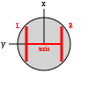
You can set the data to broadcast by using the function set_data(). This function accepts input in two forms. You can write set_data(idx, data), and this means that you set the idx-th byte to the value of data. In this case, data must be a number in the range [0,255]. Alternatively, you can write set_data(data), where data must be a table containing exactly 10 numbers in the range [0,255].
For example, if you want to broadcast the number 1 in the first byte of the message, you can write
robot.range_and_bearing.set_data(1,1)
- Receiving messages
At each time step, a robot receives a variable number of messages from nearby robots. You can know the number of messages received in a given time step if you write
#robot.range_and_bearing
Each message is stored in a table composed of data (the 10-bytes message payload), horizontal_bearing (the angle between the robot local x axis and the position of the message source; the angle is on the robot’s xy plane, in radians), vertical_bearing (like the horizontal bearing, but it is the angle between the message source and the robot’s xy plane), and range (the distance of the message source in cm).
For example, if you want to access the first byte of data of the first message received you can write
robot.range_and_bearing[1].data[1]
to access the range and the horizontal bearing of the same message you can write
robot.range_and_bearing[1].range
robot.range_and_bearing[1].horizontal_bearing
- Clearing the data
The range and bearing system can clear the received messages so they are not taken into account in the future steps. If you want to clear the received messages you can write
robot.range_and_bearing.clear_data()
RGB LEDs
Sets the color of the robot LEDs. The state of the RGB LEDs is indicated by the table
robot.leds
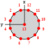
The robot has a total of 13 RGB LEDs. 12 of them are arranged in a ring around the robot body, and one (also called the beacon) is positioned at the top of the robot body.
To set the colors of a single LED, use set_single_color(idx, color), where idx is the number of the LED to set (1-12 for the body LEDs, 13 for the beacon) and color can be expressed as a string, such as "red", "green", "blue", etc., or as a triplet of numbers r,g,b.
For example, to set the color red in the first LED you can write
robot.leds.set_single_color(1, "red")
In case you wish to set all colors at once, use set_all_colors(color). For example, to set the color red in all the LEDS you can write
robot.leds.set_all_colors("red")
Omnidirectional camera
The omnidirectional camera returns a list of colored blobs, along with their position with respect to the robot center. The state of the omnidirectional camera is indicated by the table
robot.colored_blob_omnidirectional_camera
A colored blob in ARGoS corresponds to an LED. If you wish to start perceiving blobs with the omnidirectional camera you must enable the sensor.
robot.colored_blob_omnidirectional_camera.enable()
In case you want to stop perceiving blobs you can disable the camera by writing
robot.colored_blob_omnidirectional_camera.disable()
The list of blobs varies in size over time, depending on what the robots sees. You can know the total number of color blobs perceived in a given time step if you use
#robot.colored_blob_omnidirectional_camera
Each blob is stored in a table composed of distance (the distance to the blob source in cm), angle (the angle between the robot local x axis and the position of the blob source; the angle is in radians), and color (a table composed of red, green, and blue, which are three RGB components of the blob’s color in the range [0,255]).
For example, if you want to access the red component of the first blob seen by the robot you can write
robot.colored_blob_omnidirectional_camera[1].color.red
If you want to know the distance to the first blob seen, you can write
robot.colored_blob_omnidirectional_camera[1].distance
And if you wish to know at which angle the first blob is located, you can write
robot.colored_blob_omnidirectional_camera[1].angle
Robot random number generator
This table offers a set of functions to draw random numbers from a distribution. The table is defined as
robot.random
- Use
bernoulli()to get either0or1from a Bernoulli distribution withp=0.5. You can also writebernoulli(p)to set a different value forp. - Use
exponential(m)to get a random number from an exponential distribution with meanm. - Use
gaussian(s)to get a random number from a Gaussian distribution with standard deviationsand zero mean. You can also writegaussian(s,m)to set a non-zero mean. - Use
uniform()to get a random number from a uniform distribution in the range[0,1). Alternatively, you can useuniform(max)to get a number between0andmax, oruniform(min,max)to get a number betweenminandmax. If you want integer numbers, use the functionsuniform_int(max)anduniform_int(min,max).
For example, if you want yo generate a random integer number obtained from a uniform distribution, that exists between 0 and 10, you can write
myrandom = robot.random.uniform_int(10)